


Listening Article
Table of Contents
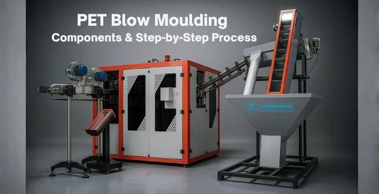
PET Blow Moulding Components & Step-by-Step Process: From Preform to Perfect Bottle
October 24, 2025
Objective of the Article
The objective of this article is to educate mineral water plant owners, managers, and industry stakeholders about the importance, features, and benefits of PET Blow Moulding Machines in modern bottle production. It aims to:
- Explain the role of PET Blow Moulding Machines in efficiently producing high-quality, durable, and hygienic mineral water bottles.
- Guide in selecting the right machine based on production capacity, automation level, and bottle specifications.
- Highlight operational and maintenance best practices to maximize productivity and reduce downtime.
- Discuss cost-effectiveness and ROI, helping businesses understand long-term benefits of investing in advanced blow moulding technology.
- Showcase trends and innovations in PET bottle manufacturing that can enhance efficiency, quality, and compliance with industry standards.
What Is PET Blow Moulding and Why It Matters?
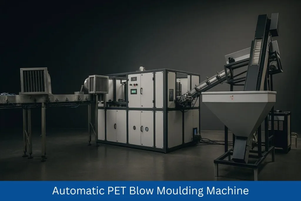
Polyethylene terephthalate (PET) blow moulding is the manufacturing method that shapes warmed PET preforms into rigid bottles and containers using a combination of axial stretching and high-pressure air blowing inside a cooled mould. It produces lightweight, crystal-clear containers for water, soft drinks, edible oil, personal care, and a thousand other products. The business value is simple: high output per cavity, low gram weight, and repeatable neck dimensions that seal perfectly with caps and closures. Modern machines-like DTPPL’s Automatic PET Blow Moulding Machine-combine servo positioning, PLC logic, multi-zone IR heating, and precise air pressure profiles to make the process faster, safer, and more energy efficient than older generations. Typical systems run from 2 cavities / 1,800 BPH to 4 cavities / 7,200 BPH depending on bottle size, preform quality, and utilities. The key to consistent results is controlling heat and strain: PET must be heated above its glass transition (~80–110 °C at the sidewall) yet keep the neck ring cool so threads stay crisp. Then, during blowing, the polymer is stretched 1.5–3.5× axially and 3–4× hoop to induce molecular orientation, giving high clarity and strength at low weight. When you understand each component-preform handling, oven, stretch system, mould, clamping, air trains, cooling-you understand how perfect bottles come off the line minute after minute.
System Overview: Stations, Motions, and Energy Flows
A linear PET stretch-blow machine can be pictured as five coordinated zones: (1) Infeed & Loading, (2) Heating & Conditioning, (3) Transfer & Indexing, (4) Stretch-Blow Moulding, and (5) Take-out & Discharge. Preforms travel in neck-supported carriers so the finish never deforms. Electrical energy powers the IR lamps and control system; pneumatic energy from the LP (low-pressure) and HP (high-pressure) compressors drives cylinders and the blowing cycle; thermal energy from the chiller and cooling tower removes heat from moulds and from compressed air aftercoolers. The PLC/HMI is the brain: it synchronizes lamp outputs, oven residence time, transfer timing, stretch-rod stroke, pre-blow timing, high-blow ramps (e.g., from 8 kg/cm² operation air to 25 kg/cm² blowing air), and exhaust. A typical DTPPL set-up lists utilities such as Heater 21 kW, Hydraulic/air blower/indexing 5 kW, HP compressor 15 kW, LP compressor 7.5 kW, Chiller 3TR ~2.625 kW, Cooling tower 20TR ~3 kW, plus refrigerated air dryer 3 kW. These numbers tell you where cost lives: ovens and high-pressure air. Good GEO-style controls reduce both by keeping lamps in closed-loop and cutting air via smart pre-blow stages. The mechanical frame holds mould thickness up to ~160 mm, clamping stroke ~120 mm, and stretch stroke ~400 mm—enough to shape bottles up to 280 mm height and 75 mm max diameter in 2-cavity 1,800 BPH configuration. Understanding this bird’s-eye map makes the next sections easy: each component either conditions PET, moves it, pressurizes it, or cools it.
Preforms: Resin, Geometry, Moisture, and Conditioning
The story starts with the preform-an injection-moulded tube with the final bottle’s neck finish already formed (e.g., 28 mm outer neck for water). Good bottles demand dry resin (≤ 50 ppm moisture for PET), precise intrinsic viscosity (IV), uniform wall thickness, and gate quality at the base. Moisture hydrolyzes PET during heating and causes low strength and haze. Plants typically dry resin before injection moulding and keep preforms bagged with desiccant; operators should avoid reheating moist stock. Geometry matters too: weight (g) and preform L/D set the stretch ratios. For a 1-L bottle with 100–1000 ml container range on DTPPL specs, a correctly chosen preform ensures the sidewall lands near 0.3–0.5 mm after blowing. Before the oven, preforms should be ambient-temperature equalized to avoid uneven heating; any scratches or oil on the body will telegraph into the bottle. Neck rings must be cool and round-they carry the preform through the machine and interface with star wheels and grippers. A quick receiving inspection-neck diameter, thread depth, visual gate check-pays back heavily in run-time and scrap reduction.

Unloading & Infeed: Bowl Feeders, Tracks, and Orientation
Bulk preforms are tipped into a bowl feeder or elevator hopper that meters them onto a gravity track. The infeed’s job is to orient neck-up, body-down and feed at a stable cadence that matches oven pitch. Photo-eyes monitor line density; if preforms back up, the hoist pauses automatically. Wear points like track side rails and neck guides must be aligned to avoid scuffing the finish. A reject gate diverts upside-down or deformed preforms using a small pneumatic kicker. The aim is gentle, scratch-free movement because defects become weak spots during stretch. At this stage, traceability begins: many plants scan bag/batch IDs at the hopper so downstream quality issues can be rooted to preform lots. Lubricants are avoided near the feed-dust or oil on bodies cause pearlescence (white blotches) after blowing. The infeed finally presents parts to the loader stars at precise spacing called cavity pitch-for DTPPL’s 2-cavity machine, a 130 mm pitch allows enough room for robust mould cooling while keeping the machine compact (approx. 63×105×115 in footprint).
Preform Loading System: Star Wheels, Transfer Arms, and Grippers
The loader transfers oriented preforms from the track to the oven carriers using star wheels or servo pick-and-place arms. The gripper mechanism clamps under the neck ring-never on threads-to avoid deformation. Since the neck must remain cool and dimensionally stable, many systems employ neck cooling (air knives or water-cooled rails) from this point forward. The PLC coordinates loading so empty carriers align with arriving preforms; encoders on the star wheel provide angular feedback. Sensors verify successful pickup; if a position is empty, the machine flags a skip so downstream functions do not attempt to blow a missing preform-important for avoiding mould fouling or stretch-rod collisions. The transfer motion should be smooth; jerk creates oscillation that later produces non-uniform heating in the oven. Operators verify gripper wear, spring tension, and timing during PMs; loose grippers cause drops, tight grippers scar the neck. Once loaded, preforms ride into the multi-zone IR oven suspended by the neck to keep bodies fully exposed to radiant heat.
Heating Module: IR Ovens, Reflectors, Temperature Zones, and Recipes
Heating is the heart of stretch-blow. The oven typically contains 8–12 IR lamp banks per lane with polished reflectors that focus energy on the body while shielding the neck. Rotating spindles spin preforms for circumferential uniformity. Each zone has percentage power set-points and pyrometer/thermocouple feedback; the HMI recipes store lamp outputs for each bottle size and preform type. The objective is to reach a sidewall temperature window ~95–110 °C (varies by IV and bottle), with axial gradients: warmer in the mid-body, cooler near the gate and shoulder to control material flow. Neck cooling rings (forced air) keep finishes below 45–55 °C to preserve thread geometry. Too hot yields sagging and base blowouts; too cold yields pearlescence and insufficient stretch. Operators monitor oven exit profiles with contactless thermometers at specified checkpoints (left/right/shoulder/base). DTPPL’s HMI with advanced PLC simplifies this: temperature indication with low-voltage circuitry ensures safety, while recipe locking prevents accidental lamp changes mid-run. Energy wise, the oven’s 21 kW heater bank is the largest consumer; closed-loop control, lamp zoning, and standby dips during pauses cut kWh per thousand bottles significantly.
Neck Handling & Protection: Thread Support, Cooling Rings, and Indexing
Throughout heating and blowing, the neck is king. It dictates cap seal and capping torque, so machines protect it with mechanical guidance and cooling. Neck rings ride on cooled rails; air knives sweep across threads to carry heat away. Indexing wheels position carriers precisely at the mould station so the neck support ring aligns with the mould mouth. If alignment is off, you’ll see witness lines or pinched flashes at the neck-shoulder junction. A mechanical or servo neck-lock clamps the finish during blowing to stop axial creep. Sensors confirm clamp engagement before allowing stretch-rod descent-a critical interlock to prevent rod-to-neck collisions. Good practice: inspect neck ovality with a ring gauge hourly and log temperatures at the finish; any drift often points to cooling airflow blockages or filter clogs. Because DTPPL designs emphasize low maintenance and user-friendly HMI, changing neck guides for a different finish during changeover is tool-light-an operator swaps rings and loads the matching recipe so cooling and stroke limits follow automatically.
Stretching System: Stretch Rods, Stroke Control, and Alignment
The stretch rod initiates molecular orientation by axially elongating the heated preform before and during air pressurization. On DTPPL machines, typical stretch stroke capacity is up to 400 mm, adjustable in the PLC with hard-stop sensors for repeatability. The rod tip often uses a polished, low-adhesion material (e.g., PTFE-coated or hardened steel) to avoid sticking at the gate; some applications use vented rods to assist pre-blow. Timing is everything: the rod begins to descend as the pre-blow starts (low pressure), reaching final stroke as high blow ramps in. If stroke is short, material piles on the base; too long and the gate thins excessively causing base crack or blow-through. Alignment is checked with blueing compound against a dummy mould; any side-load creates asymmetry in wall thickness. Rod speed profiles (fast-to-slow) help set the preferential stretch in the shoulder vs. body. Because the machine uses PLC-governed servos/hydraulics, repeatability across cavities is tight, which directly translates to balanced weights across multi-cavity tools.
Moulds: Cavities, Cooling Channels, Materials, and Venting
The mould shapes the final container. Cavities are typically machined from aluminium alloy (great thermal conductivity) with hard-coat surfaces; for abrasive applications, stainless inserts may be used. DTPPL’s 2-cavity configuration lists cavity pitch ~130 mm and supports mould thickness ~160 mm, with clamping stroke ~120 mm to open/close smoothly. Inside the cavity, conformal cooling channels circulate chilled water (8–12 °C) to pull heat rapidly—this locks in clarity and reduces cycle time. Base inserts create the push-up and petaloid patterns for carbonated or non-carbonated designs; gate pads are cooled aggressively to prevent haze around the gate. Venting micro-grooves at ribs and high-draw areas let trapped air escape during high blow; if blocked, you’ll see burn marks or short shots (under-blown corners). A neck ring set interfaces with the carrier—this ring often stays cooler than the body to keep finish crisp. Changeovers swap cavity sets, base inserts, neck rings, and recipe; quick-change dowels and water manifolds minimize downtime. Always pressure-test water circuits after any change to avoid leaks contaminating compressed air circuits or causing hot spots.
Clamping Unit: Toggle/Servo-Hydraulic Mechanics and Safety
Clamping keeps the mould halves tightly closed during the high-pressure phase. Linear machines commonly use toggle clamps or servo-hydraulic cylinders. The goal is stiffness with low inertia so index times are short. DTPPL specs point to robust clamping able to handle 25 kg/cm² blowing air without flashing. The closing curve is tuned: fast approach, slow land (to protect alignment), then high-force lock. Proximity switches verify fully closed position; only then can the PLC permit high-blow. Safety circuits (Category 3/4) include door interlocks, light curtains, and pressure relief valves; if an operator opens a guard, the machine dumps air and retracts rods to a safe position. Lubrication of toggle joints and linear guides is automated on timed cycles; missed grease leads to wear that manifests as mould mismatch lines on bottles. Shock absorbers or servo braking tame stop impacts, extending mould life. The machine’s low voltage control system reduces risk for maintenance teams while keeping diagnostics clear on the HMI.
Read Our Article: Fully Automatic Blow Molding Machine Process: A Complete Guide
High- & Low-Pressure Air Systems: Compressors, Dryers, Filters, and Valves
Air is the muscle of blowing. Two lines exist:
- Low Pressure (LP ≈ 7–8 kg/cm²): Drives actuators, pre-blow, grippers, and miscellaneous pneumatics.
- High Pressure (HP ≈ 20–25 kg/cm²): Performs the main stretch-blow.
DTPPL’s utility map shows LP compressor 7.5 kW and HP compressor 15 kW, sized to support the BPH range. Both lines pass through aftercoolers, refrigerated air dryers (≈3 kW), and coalescing filters to remove moisture and oil—wet air causes haze, fish-eyes, and valve stickiness. The HP reservoir stabilizes pressure during the peak demand when multiple cavities blow simultaneously; fast-acting solenoid or servo valves execute the pre-blow and high-blow profiles within tens of milliseconds. A pressure decay test at idle checks for leaks; loss means money because compressors are energy-intensive. Regulators per cavity let you fine-tune pressure to fix minor asymmetries; flow restrictors shape the ramp rate. Spent air exits via mufflers to reduce noise; some lines reclaim a portion of exhaust to supply LP circuits, saving energy.
Blow Cycle: Pre-Blow, Stretch-Blow, Exhaust, and Pressure Profiles
The blow cycle has four orchestrated stages:
- Pre-Blow: Low pressure (~2–5 bar) starts as the stretch rod descends. It inflates the parison softly to prevent scuffing and helps push material towards the base.
- High-Blow / Stretch-Blow: The valve switches to HP (up to 25 kg/cm²). The parison slaps the cavity walls, and orientation locks in as cooling begins. The shoulder and base are the last to freeze; managing ramp rates here controls base push-up and sidewall gloss.
- Hold: Pressure is maintained briefly to avoid elastic recovery while the PET crystallizes at the surface.
- Exhaust & Vent: Air dumps and a small vacuum/vent breaks the seal for easy ejection.
Timing is adjusted per bottle: thin-wall water bottles need shorter hold; hot-fill or CSD containers benefit from longer hold and controlled base cooling. HMI recipes store ms-level timings so operators repeat success exactly. If you see paneling after filling, revisit hold time and sidewall orientation; if base rock occurs, look at base temperature and rod contact timing.
Cooling & Crystallization: Water Circuits, Chiller & Cooling Tower Integration
Cooling determines cycle time and clarity. The mould’s internal channels connect to a chiller (3TR) delivering 8–12 °C water. A cooling tower (20TR) rejects heat from the compressor aftercoolers and sometimes a secondary circuit—tower water is warmer (28–32 °C) and never mixed with mould circuits to avoid condensation and contamination. Flow meters and quick couplers make set-up foolproof; differential temperature across the mould (ΔT) indicates whether heat is being pulled efficiently. An air dryer also aids cooling indirectly: dry air has better thermal behavior and avoids micro-droplet marks. Bottle clarity improves as cooling becomes uniform; thick bases might require dedicated base cooling jets or pulsed air after ejection. Good practice: log chiller load, return temperatures, and filter cleanliness—blockages cause hot streaks leading to haze on the corresponding cavity wall.
Ejection & Take-Out: Neck Transfer, Air Knives, and Conveyor Interfaces
After the exhaust phase, a take-out arm or stripper mechanism releases the cooled bottle from the neck ring. Air knives can dry residual condensate, and a soft belt conveyor carries bottles to visual inspection or inline leak testers. Transfer timing must avoid scuffing at high BPH; gentle acceleration profiles matter. Sensors confirm bottle presence; missing bottles can indicate mould hang-ups (often vent groove contamination). If connected to a filling line, synchronization allows “labour-free” operation—DTPPL’s machines are designed to be synchronized with bottle filling for minimal handling. Downstream, bottles may pass a spin-trimmer (if handles/flash exist on other formats), but typical PET water/oil bottles exit ready for rinsing and filling.
HMI, PLC & Sensors: Control Philosophy, Interlocks, and Diagnostics
The advanced PLC control panel is the operator’s cockpit. DTPPL configures alarm hierarchies, trend charts, and guided set-ups. Key interlocks: doors closed, mould closed, neck clamp engaged, stretch rod home, HP pressure OK, oven temp within band, cooling flow present. Recipe management locks lamp powers, blow timings, rod strokes, and pressures to the product code; a change audit records who altered what. Temperature indication in each oven zone and actual vs. set deltas are graphed live; color bands warn of drifts before defects appear. Diagnostics include I/O pages to test valves and lamps, and predictive counters for maintenance intervals (e.g., valve cycles, lamp hours). Low-voltage circuitry improves safety and reliability, while remote Ethernet access (where enabled) lets engineers support tuning. The HMI also houses OEE dashboards (availability, performance, quality), so you see the bottleneck in real time-oven starve, HP pressure drops, or mould temperature excursions.
Power & Utilities: Heaters, Motors, Pressures, and Energy Budget
A transparent utility plan is crucial for cost control. Using the snapshot specs: Heaters 21 kW, Hydraulic motor/air blower/indexing ~5 kW, LP 7.5 kW, HP 15 kW, Chiller 2.625 kW, Cooling Tower 3 kW, Air Dryer 3 kW. The big three cost centers are IR heating, HP compression, and chilling. Optimization tactics include oven standby during micro-stops, leak hunts on HP lines, air recovery for LP circuits, timed lamp zoning, and intelligent pre-blow to reduce peak HP consumption. At 1,800 BPH on a 2-cavity, plants often target < 70–90 Wh per bottle total energy; with meticulous tuning and lightweighting, even lower is possible. Operation air pressure (8 kg/cm²) powers auxiliaries; blowing air (25 kg/cm²) dictates bottle mechanical properties—never starve this line or you’ll chase inconsistent wall distribution all shift.
Quality Controls: Wall Thickness, Base Push-Up, Neck Ovality, and Tests
Quality assurance spans online checks and lab tests. Operators sample every 30–60 minutes to measure gram weight, height, diameter, neck ovality, and cap torque rings. A polarization light box reveals stress patterns; too much at the base suggests over-blow or insufficient base cooling. Wall thickness can be checked by ultrasonic probes or weight mapping after cutting sections. Top load tests ensure stacking strength; burst tests validate CSD bottles. Leak testers (vacuum or pressure decay) catch pinholes. Visual defects include blush/pearlescence (cold spots), haze (moisture or over-heat), orange peel (excess heat at the surface), bubbles (contaminants), long gate (over-stretch), and oval necks (poor neck cooling or clamp). Each defect maps back to specific components: oven zones, stretch rod timing, base cooling, HP pressure, or mould venting. Documenting defect-to-fix playbooks turns new operators into confident troubleshooters quickly.
Read Our Article: Unlocking the Potential of DTPPL’s Automatic Blow Moulding Machines
Changeovers: Cavity Pitch, Neck Finish, and Recipe Management
Changeovers are where hours are won or lost. A well-designed machine with quick-connect water manifolds, dowel-pinned moulds, and tool-less neck guides trims change time drastically. The typical sequence: (1) stop machine and purge oven (lamp standby), (2) depressurize HP/LP lines, (3) open guards, (4) swap mould set (cavities, base inserts, neck rings), (5) connect water with labelled hoses, (6) verify rod stroke limit for new height (e.g., up to 280 mm), (7) load the HMI recipe for that bottle, (8) thread sample preforms to confirm clearances, (9) ramp oven to recipe and begin trial blows, (10) fine-tune lamp zones and pressures. Experienced teams keep changeover carts with torque wrenches, O-rings, and spare sensors. With practice, a 2-cavity water-to-oil bottle change can be done in under 90 minutes; the biggest variable is cooling stabilization—wait until return water temperatures settle before finalizing.
Maintenance Playbook: Lubrication, Alignment, and Preventive Jobs
Reliability stems from small, regular tasks. Daily: clean oven filters, inspect lamp tubes for darkening, grease toggle points if not auto-lubricated, drain air receiver condensate, check HP/LP pressure and dryer dew point. Weekly: verify stretch rod concentricity, mould vent cleaning, gripper wear, sensor alignment, chain tension on carriers. Monthly: calibrate oven temperature sensors, check chiller flow rates, replace air filters, audit energy usage vs. BPH. Annually: overhaul HP valves, rod bushings, and hydraulic seals if used. DTPPL’s low-voltage control and PLC diagnostics reduce unplanned stops by surfacing early signs—slow valve response or rising motor current. Keeping a spares matrix (lamps, valves, seals, proximity switches) prevents long downtime. Record mean time between failures (MTBF) for critical parts to refine the PM schedule over time.
Common Defects & Root Causes: Blush, Pearlescence, Haze, and Burst
- Pearlescence (white, chalky streaks): Preform too cold; increase mid-oven zones or reduce line speed.
- Haze (milky, non-crystalline areas): Moist preforms, overheated surface, or poor cooling-check dryer logs, lamp power, and water flow.
- Base Blow-Through / Gate Whitening: Excessive rod force or too-hot gate-reduce stroke, add base cooling, balance pre-blow.
- Ribs not formed / under-blown corners: HP pressure low or vent blocked-raise pressure or clean vent grooves.
- Neck Ovality / Thread Damage: Neck cooling insufficient or clamp misalignment-service cooling ring and neck lock.
- Orange Peel / Rough Surface: Overheating; lower lamp power or increase rotation speed.
- Paneling after fill: Low orientation; increase stretch, adjust ramp, or tweak oven profile. Each fix points back to a component and recipe value, reinforcing the importance of disciplined parameter control.
Throughput & OEE: BPH Calculation and Line Balancing with Fillers
For a 2-cavity / 1,800 BPH machine, cycle time is roughly 4 seconds (including index, close, blow, open, eject). Uptime hinges on starve/stoppage events—infeed jams, HP pressure dips, or downstream conveyor backups. OEE (Availability × Performance × Quality) surfaces the biggest leaks: e.g., Availability drops from changeovers and PM, Performance from oven speed limits, Quality from rejects. Because DTPPL machines synchronize with the filling line, aim to balance filler BPM with blower BPH plus a buffer: maintain 5–10 minutes of accumulation to absorb micro-stoppages. Tracking events per session in GA is analogous in the digital sphere; on the shop floor, track events per hour (alarms, micro-stops) and attack the top three weekly.
Safety, Compliance & Documentation
Safeguards include interlocked doors, two-hand jog, pressure relief valves, and lockout/tagout procedures. Hot surfaces in the oven are guarded; signs warn of IR exposure. Documentation should include material safety data, utility drawings, pneumatic schematics, recipe change logs, and inspection records. For export or food-grade packaging, maintain traceability from resin lot to pallet ID; store process parameters with each batch. Electrical panels should conform to low-voltage directives; compressed air systems must pass pressure vessel inspections where applicable. Training operators on burn risk, pinch points, and hearing protection around HP exhaust is essential for a zero-harm culture.

Step-By-Step Production Walkthrough (Operator’s Perspective)
- Start-Up & Checks: Confirm utilities-8 kg/cm² LP, 25 kg/cm² HP, chiller at setpoint, cooling tower running, dryer dew point within spec. Warm oven to recipe, verify moulds connected and leak-free.
- Load Preforms: Tip bag into hopper, scan lot, start elevator. Watch the orientation track and purge rejects.
- Engage Recipe: On the HMI, select bottle code; PLC sets lamp powers, rod stroke (≤ 400 mm), pre- and high-blow timings, and pressures.
- Dry Run: Cycle without preforms to verify indexing, clamp, rod movement, and sensor health.
- Run with Preforms: Start loading. Confirm oven exit temperatures with an IR thermometer; adjust zone 3–5 for shoulder/body balance.
- First Articles: Inspect the first 10 bottles-weight, height (≤ 280 mm), diameter (≤ 75 mm), neck gauge, visual clarity. Tweak HP pressure and hold time as required.
- Steady State: Monitor return water temps, HP reservoir gauge, and alarm log. Keep an eye on air dryer and filter differential pressure.
- Sampling: Every hour, log dimensions, torque ring, and stress pattern. Clear vent grooves and wipe neck rings.
- End of Shift: Put oven to standby, depressurize HP, purge moisture traps, back up recipe changes, and fill the production report (good/reject/causes).

Component-to-Feature Mapping for DTPPL’s Automatic PET Blow Moulding Machine
- Forming Envelope:Cavity pitch ~130 mm, mould thickness ~160 mm, clamp stroke ~120 mm, stretch stroke up to 400 mm, 2–4 cavities, 1,800–7,200 BPH.
- Product Range:Height up to 280 mm, OD up to 75 mm, volume 100–1000 ml, neck OD ~28 mm.
- Power & Utilities:Heaters 21 kW, Hydraulic/air/indexing 5 kW, HP 15 kW, LP 7.5 kW, Chiller 3TR ~2.625 kW, Cooling tower 20TR ~3 kW, Air dryer 3 kW; LP 8 kg/cm², HP 25 kg/cm².
- Control & Safety:Advanced PLC + HMI, temperature indication, low-voltage circuitry, recipe management, synchronization with filling line, simplified maintenance.
- Quality Enablers:Precise neck handling, multi-zone IR heating, fast air valves, efficient mould cooling, FAQ-style diagnostics for operators.
Bottle Design & Preform Selection: Getting Stretch Ratios Right Before You Ever Press “Start”
Design decisions made at the desk decide how hard the machine must work on the floor. Every target bottle geometry—height, shoulder angle, base style, label panel depth, and thread—maps to a preform weight, length, and wall thickness profile that produces healthy axial (λa) and hoop (λh) stretch ratios. For water bottles in the 100–1000 ml range of DTPPL’s platform, a safe heuristic is λa ~ 2.0–3.0 and λh ~ 3.0–3.8 measured at mid-body. If the preform is too heavy, you’ll struggle to distribute material, causing panel thick spots and high gram costs. If it’s too light or too short, you’ll over-stretch, thinning the gate or producing pearlescence on ribs. The neck finish (28 mm is common) is fixed by the cap system and doesn’t stretch; that’s why neck cooling and neck handling are so critical. Start by drawing a mass budget: decide how many grams must live in the base (for push-up and stability), shoulder (for top-load), and body (for clarity). Then confirm that mould ribbing and panel features can pull materialwhere needed—shallow ribs with generous radii avoid stress risers and haze. Hot-fill designs demand higher crystallinity in targeted zones and often use panels to absorb vacuum; that means longer oven residence, hotter mid-zones, and base inserts designed for better heat resistance. Carbonated beverage (CSD) designs rely on petaloid bases to anchor carbonic pressure; their preforms are heavier at the gate with controlled stretch-rod contact. DTPPL’s quick-change base inserts let you tune these variants without a full mould swap. Finally, snag a finite element simulation or at least a spreadsheet model—map preform circumference to bottle circumference along the height to confirm λh stays within window. This 30-minute calculation saves weeks of trial-and-error and ensures the machine hits nameplate speeds like 1,800 BPH (2-cavity) or 5,400–7,200 BPH (4-cavity) without chasing defects.
Read Our Article: Blow Moulding Machine: Q&A Guide for Automatic & Semi-Automatic Models
Parameter Recipes for Common Formats: Water, Edible Oil, and CSD
Below is a starter recipe table operators can adapt on DTPPL machines. Always validate with your QA standards and adjust for resin IV, ambient temperature, and mould cooling.
| Format | Volume | Preform (example) | Oven Zones (1→8, % power) | Exit Body Temp | Stretch Rod Stroke | Pre-Blow (bar / ms) | High-Blow (bar / ms hold) | HP Exhaust (ms) | Notes |
|---|---|---|---|---|---|---|---|---|---|
| Still Water | 500 ml | 10–12 g, 28 mm | 45/55/60/65/65/60/55/45 | 98–102 °C | 290–310 mm | 3.0 / 120 | 22–24 / 350 | 120 | Keep shoulder cooler to avoid washboard; fast rod then decel near base. |
| Edible Oil | 1 L | 20–24 g, 28 mm | 55/60/65/70/70/65/60/50 | 102–108 °C | 330–350 mm | 3.5 / 150 | 23–25 / 420 | 140 | Longer hold for rigidity; increase neck cooling airflow to maintain thread. |
| CSD | 600 ml | 24–27 g, 28 mm | 50/60/68/72/72/68/62/55 | 100–106 °C | 300–320 mm | 4.0 / 180 | 24–25 / 500 | 160 | Focus on base cooling; verify petaloid formation and burst > 12 bar. |
How to deploy on the HMI: pick the product code, verify LP 8 kg/cm² and HP 25 kg/cm² availability, preload rod stroke (≤ 400 mm limit), and run five first-off articles. Measure weight and dimensions, then tweak only one axis at a time—lamp, pressure, or stroke—to converge. Recipes in DTPPL controls allow notes; log the resin lot, dew point, and chiller setpoint so future runs repeat flawlessly.
Troubleshooting Matrix: Map Symptom → Machine Component → Corrective Action
| Symptom | Likely Root | Component to Inspect | Fast Fix | Deeper Corrective |
| White pearlescent streaks | Body too cold, moisture | Oven zones 3–6; air dryer dew point | +5–10% power mid-zones; slow index | Dry preforms properly; service dryer; check rotation motors. |
| Haze around gate | Gate too hot / insufficient cooling | Base insert cooling, rod timing | Add base cooling; start pre-blow earlier | Reduce zone 7–8 power; re-lap rod tip; verify chiller flow. |
| Base blow-through | Excessive stretch or hot gate | Rod stroke, base temp | Shorten stroke 5–10 mm | Change preform; add base cooling jet; polish gate pad. |
| Oval neck / capping leaks | Neck overheating / clamp misalign | Neck ring cooling, neck lock | Increase neck air; re-zero neck clamp | Replace worn neck guides; align mould mouthpiece. |
| Under-blown ribs/corners | HP low, vent blocked | HP regulator/valve; cavity vents | Raise HP 1–2 bar; clean vents | Recut vent grooves; inspect HP valve response time. |
| Orange peel / rough gloss | Surface overheated | Oven zones 1–2 and 7–8 | Reduce surface zones 5–10% | Increase rotation speed; tune reflector positions. |
| Paneling after filling | Weak orientation / thin walls | Stretch profile; hold time | Increase hold 50–100 ms | Adjust preform or redesign rib geometry. |
Keep a defect board near the HMI. DTPPL’s alarm history plus this matrix shortens diagnosis time. Always verify utilities first—most “mystery defects” are air pressure dips or chiller malfunctions.
Utilities & Sizing Calculations: Air, Cooling, and Electrical
Sizing utilities correctly ensures the rated BPH is attainable. High-Pressure Air: Estimate consumption as (cavity volume + manifold losses) × blows per minute × safety factor. A 500-ml bottle might see ~1.0–1.2 L(STP) of HP air per blow after recovery; at 30 cycles/min on 2 cavities, that’s ~60–72 L/min plus losses; multiply by ~3–4× for pressure and dynamics to size compressor flow (free air delivery). DTPPL’s guidance HP 15 kW comfortably supports the 2-cavity spec when paired with a receiver (≥ 500–1000 L) to buffer peaks. LP Air: Valves and grippers add ~0.2–0.4 L per cycle per cavity; with pneumatics and purge, a 7.5 kW LP compressor is typical. Always include a refrigerated dryer and coalescing filters (0.01 μm class). Cooling: Moulds need 8–12 °C supply at 2–4 L/min per cavity; that’s 4–16 L/min on 2–4 cavities. A 3TR chiller (≈10.5 kW cooling) handles typical heat, while the 20TR cooling tower extracts compressor and ambient heat from aftercoolers and hydraulics. Electrical: The 21 kW heater is the main load; diversity factor applies because lamps PWM. Provide a 40–50 kVA feeder for a 2-cavity cell including auxiliaries, with 415V, 3-phase, good earthing, and surge protection. Instrument kWh/bottle; when this KPI trends up, hunt leaks, lamp aging, or recipe drift.
Energy Optimization Playbook: Lower kWh Without Lowering Quality
Energy in PET blow moulding concentrates in IR lamps and HP air. Attack both. For ovens, tune lamp zoning so every zone works—not one zone blazing to compensate for a cold neighbor. Use reflector cleaning schedules; dusty reflectors waste 5–10% power. Adopt oven standby: if the infeed starves for 60 s, PLC dips zones to 30–40% and recovers in <10 s when preforms return. Rotate carriers diligently; static hot spots mean overcompensation elsewhere. On the compressed-air side, install HP leak-detection with ultrasonic guns—every tiny hiss at 25 kg/cm² equals money. Enable air recovery for LP circuits using bleed air from exhaust; many plants save 10–20% LP energy this way. Optimize pre-blow: too much pre-blow steals HP work but inflates consumption; too little causes scuffing and defects. DTPPL’s fast valves allow shorter, sharper profiles so pressure acts where it matters. Watch dew point: wet air increases reject rate, and scrap is the worst energy waste. Lastly, schedule lamp replacement by hours-on rather than by failure; aging lamps drift and force recipe creep. A weekly dashboard of kWh per 1,000 bottles, HP compressor duty cycle, and chiller ΔT keeps everyone aligned on savings.
Integration with Filling & Downstream: The “Labour-Free” Line
DTPPL machines are designed to synchronize with bottle filling lines, turning preforms into filled, capped product with minimal human touches. The blower hands off to a rinser/filler/capper (RFC) via an air conveyor or neck-handling conveyor. The magic is pitch and tempo alignment: blower BPH must comfortably exceed filler BPM with a 5–10 min buffer on accumulation tables so micro-stops don’t ripple. Use the HMI’s line sync I/O: when the filler slows, the blower throttles index speed and puts ovens into semi-standby rather than dumping rejects. Add inline leak testers for CSD; for water and oil, periodic offline tests might suffice. Downstream, labellers prefer dry, scuff-free sidewalls—hence the air knives at take-out. For hot climates, add a conditioning tunnel so bottles arrive to labeller near 25–30 °C. Data-wise, connect the blower’s OEE tags to the plant MES so maintenance can correlate stoppages with HP pressure events or chiller alarms. This is where DTPPL’s advanced PLC panel shines—clean signals, clear alarms, and documented recipes reduce blame-shifting and accelerate root cause analysis when the line hiccups.
Commissioning, FAT/SAT & Validation: Making Day 1 Look Like Day 100
Great projects start with a crisp Factory Acceptance Test (FAT) and Site Acceptance Test (SAT). For the blower, FAT should include: (1) electrical and pneumatic schematics walk-through; (2) dry cycle at nameplate speed; (3) oven heating uniformity test with temp strips; (4) HP/LP leak tests; (5) HMI recipe load/save and audit trail; (6) safety circuit validation (interlocks, e-stops). SAT repeats these with your preforms, caps, and moulds plus a 24-hour reliability run at target BPH. Acceptance criteria: rejects < 1–2%, energy < target Wh/bottle, neck gauge pass rate ≥ 99.5%, and documented first-off recipe. Capture a Golden Sample Pack—ten bottles with all dimensions recorded and photo-documented. Train operators on start-up, changeover, sampling, and PM. Finally, institute a 30-60-90 day optimization plan: week 1 balances lamp zones, week 2 trims HP consumption, month 1 finalizes changeover SOPs. With DTPPL’s low-voltage control architecture and clear HMI, new teams typically stabilize quickly and hit steady OEE within the first few weeks.
Advanced Variants: Hot-Fill, Handleware, Wide-Mouth & Reheat Considerations
Beyond standard water and oil, PET blow moulding spans hot-fill juices, wide-mouth jars, and handleware. Hot-fill bottles see product at ~85–92 °C, so sidewalls need higher crystallinity and panels for vacuum absorption. Recipes raise oven temperatures, lengthen holds, and use crystallizing moulds with specific surface finishes. Wide-mouth jars (63–120 mm finishes) stretch less axially; preforms are short and heavy, and ovens must heat more uniformly near the shoulder—add auxiliary shoulder heaters if needed. Handleware often relies on injection-moulded handles over-blown into pockets or post-inserted; stretching must not trap air near the handle pocket—extra venting is mandatory. Reheat of regrind preforms is generally discouraged; if used, keep ratios low and verify IV, acetaldehyde, and color. DTPPL’s machines accommodate these with modular mould sets, tunable rod profiles, and extended oven zoning. Operators should keep separate recipe families; a hot-fill recipe won’t behave on a light 500-ml water bottle, and mixing them invites scrap.
Sustainability & Light weighting: Do More with Fewer Grams
Sustainability in PET isn’t just about recycling; it’s about light weighting without performance loss. Two levers dominate: (1) Better orientation so less material achieves the same top load and drop strength; (2) Geometry that supports loads intelligently (ribs, label panel curvature, base push-up depth). Start by trimming 1–2 grams from a stable bottle and run a disciplined DOE: vary rod stroke, pre-/high-blow timing, and oven gradients, measuring top load, creep, and burst. Often you’ll find 0.5–1.0 g comes “for free” with smarter parameters. Next, consider rPET blends (e.g., 10–30%); they can alter heat absorption—adjust oven zones accordingly to maintain clarity. DTPPL’s steady neck cooling helps keep finishes crisp even as bodies get thinner, an essential for cap torque reliability. Track kWh/kg PET as a sustainability KPI beside kWh/bottle; a lighter bottle automatically reduces energy per unit of product delivered. Finally, design for label removal, color minimization, and single-resin closures so post-consumer recycling streams improve. PET’s circularity is real—machines that mold with precision are part of that story.
![]()
Conclusion: Precision Components, Disciplined Control, Repeatable Excellence
From the first preform in the hopper to the last bottle on the pallet, perfect PET containers are the sum of purpose-built components—IR ovens with smart zoning, neck-centric handling, fast clamping, tightly cooled moulds, and clean, dry air—all orchestrated by an advanced PLC. DTPPL’s Automatic PET Blow Moulding Machine embodies those principles with robust mechanics, low-voltage, diagnostic-rich controls, and utility-balanced design (21 kW heaters, 15 kW HP, 7.5 kW LP, 3TR chiller). When operators pair these assets with sound recipes, quality sampling, and energy-aware habits, outputs like 1,800 BPH on 2 cavities or 5,400–7,200 BPH on 4 cavities become everyday facts, not brochure promises. Follow the component-by-component guidance, use the tables as your jumping-off point, and your line will deliver clearer, lighter, stronger bottles—reliably, shift after shift.
FAQs
1) Which single parameter should I tweak first when bottles show pearlescence?
Start with oven mid-zones (typically zones 3–6). Pearlescence is a classic symptom of insufficient body temperature or moisture. Add +5% power to mid zones, slow index slightly, and confirm dryer dew point (≤–20 °C recommended). Only after that consider stroke or pressure changes.
2) How do I choose between higher pre-blow or longer high-blow hold for top-load improvement?
If sidewalls are scuffed or base material isn’t reaching corners, raise pre-blow first to improve distribution. If shape is good but creep/top load is weak, extend high-blow hold 50–150 ms to lock orientation. Pre-blow shapes; hold strengthens.
3) Why does my neck ovality drift after 2–3 hours even though initial bottles were perfect?
Likely neck cooling degradation: clogged filters, diminished blower output, or ambient heat raising the neck ring temperature. Check airflow, clean nozzles, and verify neck lock alignment. A backup sign is rising cap torque variance on the filler.
4) What maintenance has the biggest ROI on uptime?
Three quick wins: (a) HP leak hunts with ultrasonic detectors; (b) reflector cleaning and lamp-hour tracking to keep ovens efficient; (c) vent groove cleaning every shift to prevent under-blow defects. These prevent chronic micro-stops and scrap spikes.
5) How do I document a “Golden Recipe” so any shift can reproduce it?
On DTPPL’s HMI, save a named recipe with version and notes (resin IV, dew point, chiller setpoint). Print the QA sheet with bottle dimensions and attach photos of stress patterns. Keep a bottle sample in a labeled bag. Lock the recipe to admin edit only; shifts load, run, and log.

Director – Global Marketing and Sales
Mr. Bhavesh from Dharmanandan Techno Projects Pvt. Ltd. has played a pivotal role in elevating the DTPPL brand to the global stage, leveraging his exceptional expertise in marketing and communications. He is committed to helping clients achieve significant growth while strengthening their own brands. Dharmanandan Techno Projects Pvt. Ltd. is a leading manufacturer and supplier of water purification systems and turnkey solutions for mineral water plants. With years of experience in designing and delivering high-quality water treatment solutions, the company provides end-to-end services, including system design, installation, maintenance, and ongoing support. Specializing in scalable and customizable water plants, DTPPL has successfully served industries worldwide, ensuring clean and safe drinking water across diverse applications.